


Plant
-
1. Integrated Module Designing TechnologyWhen executing a modular project, the modular proportion of the project is determined based on the results of the feasibility study, while the clustering designing method is applied during the FEED (Front-End Engineering Design) phase, which is how we make the optimal plot plan (layout) for modulization. Also, if a rotating device is needed in a module, we prevent resonance with our vibration control/management technology.
-
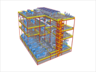 An optimized plot plan utilizing the module clustering methodWith clustering, which is a method in which machines, equipment, and instruments that are spread on a flat surface are structured into a single module in a vertical and compact rearrangement, we minimize the space needed for structures and equipment while reducing the length of piping and cables. With such a plan, our modules provide an optimized plot plan while reducing the total installation cost.
 -
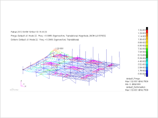 Vibration engineering for rotating devicesIn module clustering, we manufacturer and transport the system with the rotating devices that cause vibrations located inside the module. This requires vibration analysis and engineering capabilities to avoid resonance between these rotating devices and steel structures. We apply stepwise FEED and EPC execution procedures and the vibration analysis engineering method.
-
-
2. Technologies to Manage the Stability in Module TransportationEnsuring safety is essential to prevent an overturn of the module while being transported inland. On the other hand, flaws in a sea transportation plan may result in excessive steel structures in design, using up more steel structures than is necessary. To ensure safety in transportation and economy in design at the same time, our modules are designed utilizing BIM -based data, safety review technologies, analysis of the conditions in the sea using motion analysis, and sea transportation engineering technologies.
-
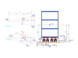 Module Weight management and C.O.G. control technology based on BIMUsing the BIM data, we calculate the weight of the module and identify the center of gravity (C.O.G.) to review the safety of inland transportation and site installation strategies. This also helps us calculate the necessary S.A.F. (sea acceleration force). Also, with the progress of the detailed designing, the integrity of the BIM increases. The resultant, highly accurate weight information and the center of gravity are controlled to match the actual weight measurement data within the tolerance in the phase of module shipment. This prevents any delays in the shipping schedule.
 -
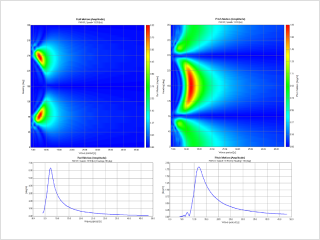 Securing stability in sea transportation through motion analysisIn the designing process of sea transportation, we consider the route of the voyage, weather at sea, and information of the vessel and use Moses, Octopus, and other motion analysis programs to calculate the S.A.F. (sea acceleration force) that is generated by waves. With this, we ensure the credibility of the information on the forces that are applied to the streel structure, which prevents over-engineering or under-engineering of these steel structures and thereby secures the economy and safety of the structure. Also, we are prepared for the need for additional strengthening due to changes in the S.A.F. while in maritime transit.
-
-
3. Precision Control Technology for Module ManufacturingWe also apply the AWP (advanced work package) that is based on the POC (path of construction) in the module manufacturing phase to share the current status of manufacturing management and collaborate with the module manufacturer. Also, the module that has been completed by the module manufacturer is 3D-scanned to conduct an installation simulation in consideration of the site conditions. This way, we can prevent mismatching defects between modules when the modules are actually installed at the site.
-
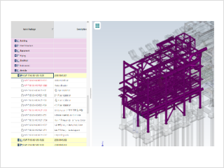 Module manufacturing management by applying the AWPWe apply and share the AWP in each stage that is performed at the manufacturer, such as the preparation of the shop drawing, delivery of materials, manufacturing, assembly, etc., as well as setting up of the schedule to build a system of collaboration with the manufacturer. Especially for the manufacturing of pipes, we utilize the CWP (construction work package) Auto Assign Program to perform the Sheet Break (breaking down the job into easily workable chunks) of the piping ISO (isometric drawings) within the module and separate them in the BIM to enhance the accuracy in the piping manufacturing phase.
- Project references : US GTP Project, S-OIL Shaheen Project
-
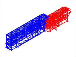 Dimensional control based on 3D scanningThe connecting parts of completed modules are measured using a 3D scanner and an electronic distance measurement device, which is followed by a simulation of the installation phase to control the manufacturing dimensions of modules within tolerance limits. This enables a Single Weld Hookup of the connecting pipes between modules, making the insertion of the pup-piece spool between different modules. This may improve the construction time, cost, and quality.
- Reference projects: S-OIL RUC Project, Singapore Spring Project, US GTP Project, etc.
-